How to Identify Manifold vs. Nozzle Heaters Using Resistance Testing
In an ideal injection molding shop, every mold comes with a crystal-clear wiring diagram. But in the real world of fast-paced production, documentation gets lost, labels wear off, and technicians are left facing a heavy-duty connector with dozens of unmarked pins.
When troubleshooting a hot runner system, misidentifying a zone can lead to severe issues—like overheating a delicate nozzle or underheating a massive manifold.
Fortunately, you don’t need a wiring diagram to solve this puzzle. By leveraging basic electrical physics, you can accurately distinguish between a Manifold Heater and a Nozzle Heater in less than 5 minutes using a standard digital multimeter. Here is how.
The Underlying Physics: Ohm’s Law at Work
The secret to identification lies in the Power Dissipation Profile of the components:
Manifold Heaters: A hot runner manifold has a large steel mass and requires high power to maintain thermal balance across the system (typically 1000W – 4000W+).
Nozzle Heaters: Individual nozzles have a much smaller mass and operate with independent, lower-power heating bands (typically 200W – 800W).
According to Ohm's Law (P = U² / R), at a standard factory voltage (e.g., 230V), power is inversely proportional to resistance. Therefore:
- Higher Power = Lower Resistance (Manifold Heaters)
- Lower Power} = Higher Resistance (Nozzle Heaters)
Step-by-Step Diagnostic Procedure
SAFETY WARNING: Before performing any measurements, you MUST shut down the main power of the temperature controller and unplug the mold cables. Never measure resistance on a live circuit to prevent high-voltage shock and instrument damage.
Step 1: Prepare Your Equipment
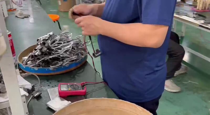
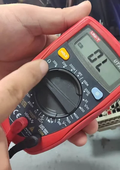
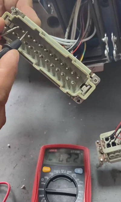
Switch your digital multimeter to the Resistance (Ω) mode. Set it to auto-range, or manually select the 200Ω or 2000Ω scale
Step 2: Measure the Connector Pins
Locate the paired heater pins on the heavy-duty connector (typically labeled sequentially, such as 1-2, 3-4, etc.). Place your multimeter probes on the pairs and record the stable resistance values.
Step 3: Apply the Decision Rule
Compare your recorded values against the standard electrical profiles (calculated at a standard 230V operating voltage):
| Heater Type | Typical Power Range | Typical Resistance Range (Ω) |
|---|---|---|
| Manifold Heater | 1500W – 3000W | Approx. 17.6Ω to 35.2Ω |
| Nozzle Heater | 250W – 600W | Approx. 88.0Ω to 211.6Ω |
- Rule of Thumb: If the resistance reads between 15Ω and 40Ω, it is a Manifold Heater. If it reads between 80Ω and 200+Ω, it is a Nozzle Heater.
Preventive Maintenance (PM) Best Practices
To optimize your injection molding uptime, move from reactive troubleshooting to preventive maintenance:
- Establish a “Resistance Fingerprint” Database: During new mold commissioning, measure and record the cold resistance of every single heater zone and thermocouple. Affix this baseline data chart directly onto the mold’s terminal box for instant reference.
- Perform Regular Insulation Tests (Megger Test): Coil resistance alone won’t reveal internal degradation. During routine PM, use a 500V Megohmmeter to check insulation resistance from the pins to the ground (mold frame). It should strictly read ≥20MΩ to prevent unexpected short circuits caused by ambient moisture or material leakage.